


Innovation
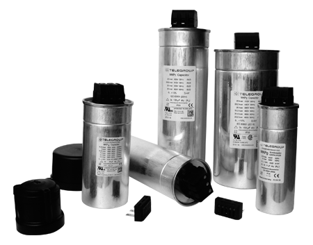
TELEGROUP, was the first Company
in Italy to marry entirely both the Three-Phase technology,
abandoning the archaic Single-phase type, and the typology of
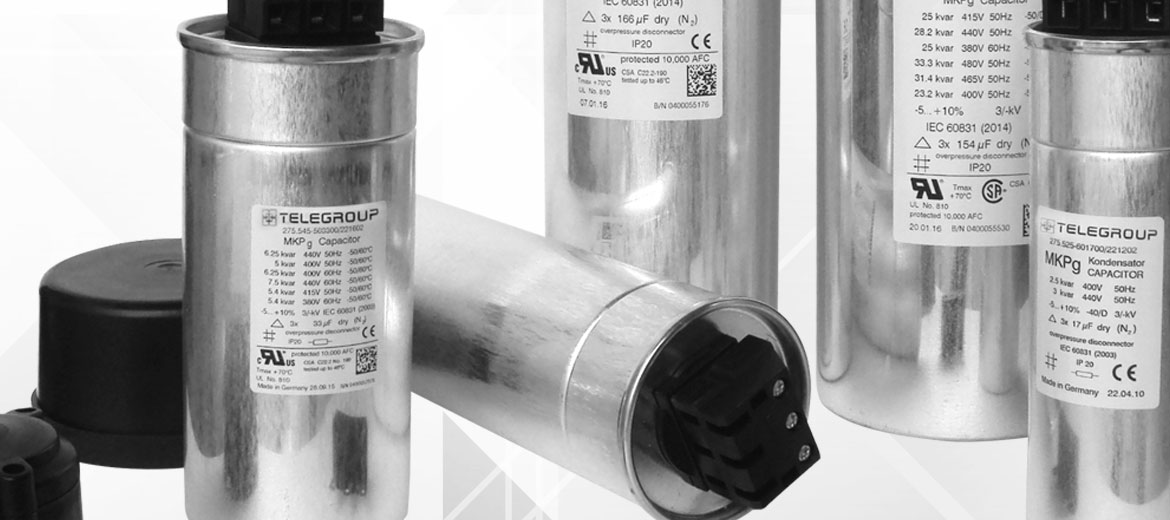
Nitrogen (N2) Gas filled Capacitors filling.
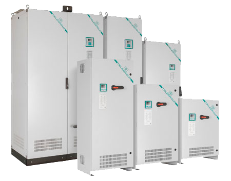
With the strength of being able to count on a very high quality
component, TELEGROUP is now recognized as a highly specialized
company in the production of Low Voltage PFC systems, installed in
over 40 countries worldwide.
Services
NETWORK ANALYSIS
SPECIAL SOLUTIONS
TECHNICAL SEMINARS
COMMISSIONING
CHECKING ELECTRICAL BILLS
- Professional software
- Online sizing of needed Power Factor Correction System
- Verify the Economic and Energy Saving
- Start
- Catalog, technical sheets and useful material
- See download
FAQ
- How is cos phi calculated?Open
or Close
To calculate the cos phi of the plant, it is necessary to have data on the consumption of Active Energy (kWh) and Reactive Energy (kVArh), or Active Power (kW) and Apparent Power (kVA).
These values can be found in the electricity bill or through a network analysis. If in possession of kWh and kVArh
Download Pdf for more information >> - How is the reactive power of an automatic PFC
system calculated?Open or Close
To define the required reactive power of an automatic PFC system, it is essential to have:
• Active Power (kW)
• Initial Cos φ (also deduced from the Active and Reactive Energy consumed, see above)
• Desired Cos φ
Formula: Q = P * k
• Q: Necessary reactive power (kVAr)
• P: Active Power (kW)
• K: Cos φ coefficient from table >> attachment 1
Example
Plant with active power 650 kW and initial Cos φ 0.75, to be brought to 0.95.
What is the necessary reactive power?
500 kW *0.553 (coefficient K for cos phi from 0.75 to 0.95)
= 276 kVAr - How can I choose the appropriate power of an
automatic PFC system?Open or Close
It is advisable to oversize the necessary reactive power by 15-20% in order to maintain an average Cos φ of 0.95 even with load variations and/or future extensions.
- How is the reactive power of a fix PFCs
calculated?Open or Close
Compensation of MV/LV Trafo
For economic reasons, it is advisable to compensate the reactive power that the Transformer absorbs for the magnetisation of the core and for the winder reactors.
The choice of Reactive power can be made based on table >> attachment 2
Compensation of Asynchronous motors
The reactive power necessary for the power factor correction of Asynchronous Motors is chosen from the following table >> attachment 2
It is always advisable in these situations to take into account the possible self-excitation of the capacitors, which is why the installation of an automatic PFC system rather than a fix one is preferred.
It is always advisable to take into account possible operation of the Motor as a self-excited generator, and this can result in voltages that are considerably higher than those of the network.
Testimonials

“Working with Telegroup inspired confidence and brought efficiency to our projects, through their high-quality PFC and solution for every task. Their team of engineers is very knowledgeable and supportive, respond quickly and effectively while clearly communicating. We are proud to be your business partner in Ghana.”
POWER & CO. ENGINEERING Ltd - Eng. Hayssam Halawi, Owner
“Telegroup has been our supplier for the last three years and we are really enjoying working with them. They offer us a high quality product that the customers love and their technical support is great! Even though we are in Australia and have an eight hour time difference, the team at Telegroup ensures we do not wait too long for a reply to our questions. A great company lead by great people, we recommend using Telegroup for all PFC projects.”
ADAPT AUSTRALIA Pty Ltd - Mr. Peter Sandars, Mr. Yane Coceski, Mr. Steve Marshall
“Energy Monitoring Ireland is a very satisfied customer of TELEGROUP S.r.l for the past 3 years. We find the quality of the products, technical assistance and delivery superior to any other suppliers providing Power Factor Correction solutions in the past. We have successfully installed systems in many prestigious projects in Ireland including hospitals, commercial and industrial applications.”
ENERGY MONITORING Ltd - Mr. Mark Leahy, Mr. Rory Leahy
“ITALIAN TOP QUALITY, The equipment quality combined with the experience and friendliness of staff makes TELEGROUP a brand that we like to work with.”
EFICSEVEN Lda - Mr. José Neves
"Working with TELEGROUP gives to our client fiability, safe and all the support they need pre-sales and post-sales, from low powers with few engineering requirements to high powers wich requires a personalised study and a technical support the engineery or the client for the best choice. We are very confident with TELEGROUP"
GESTINEL S.L. - Mr. Joan Salles Sen